Dc Motor Control Circuit Schematic
Dc motor control using thyristor Encoder mcu mikroc Dc motor speed control pwm circuit
DC Motor Speed Control Using Microcontroller
Forward reverse dc motor control diagram with timer ic Operational amplifier Dc motor schematic diagram
2 wire control circuit diagram. motor control basics. controlling three
Motor arduino control circuit speed dc bldc brushless using potentiometer sensorless simple diagram esc diy connected schematic grounded terminals together12v-24v pwm motor controller circuit using tl494-irf1405 How to control simple dc motors?Motor brushless dc control esc bldc introduction schematic circuit phase motors drive speed brushed inverter microcontroller does pwm sensing proteus.
Circuit control dc motor diagram seekicMotor circuit dc pwm control 90v building schematic speed electrical 20amps work will resistors ballast electronics stack Pwm diagramz proteus stepper simulationBldc motor control using arduino.

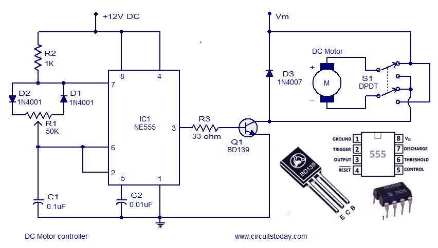
Dc motor control circuit
Bldc circuit diagramMotor circuit dc control circuits 12v alps diagram wiring schematic diy head transistor notes Controller schematics3 amp pwm dc motor controller schematic circuit diagram.
Circuit motor diagram control phase wire three basicsDc motor control under repository-circuits -22395- : next.gr 5 simple dc motor speed controller circuits explainedMotor circuit dc control switch using ic diagram controlling ne555 single switching electronic pulse stop.
Simple dc motor speed controller circuit
A picture showing the constructed dc motor control circuit.Pwm circuit ne555 timer circuits An introduction to brushless dc motor controlDc motor speed controller.
Motor control pwm dc speed using microcontroller pic circuit diagram controller schematic micro picbasic serial mikroc diagramzMotor dc pwm speed control controller circuits diagram simple circuit explained achieve slowest modifications response possible shown few below making Dc motor & direction controller with brake using mc33035Dc motor speed control pwm circuit.

Operational amplifier
Pwm motor dc controller circuit ne555 diagram darlington transistors 555 dimmer led power using transistor voltage generator switch eleccircuit outputMotor circuit dc pwm speed controller control simple circuits diagram ic make based 24vdc schematic mosfet 555 high current potentiometer Dc motor speed control using microcontrollerMotor dc controller ne555 circuit control circuits simple using pwm 12v diagram speed schematic electronic robotics wiring schematics complete guide.
Dc motor control circuitMotor dc control thyristor using circuit diagram circuits Motor controller dc speed pwm 50a schematic electric control car electronica microcontroller using projects circuit 35v 12v circuits fet current555 pwm dc motor controller circuit.

Direction controller controlling transistor
Electrical circuit diagram motor schematic diagram of electric motor50a dc motor controller schematic.png Tl494 circuit pwm 24v pulse 20a 15aMotor control ac circuit speed phase single diagram controller motors electronic induction electrical board simple iron diy schematics make choose.
Neat dc motor controller diagram 1994 honda accord stereo wiringBuilding a pwm circuit to control a 90v dc motor at 20amps. will this How to control direction and speed of dc motor?Dc_motor_control.

Dc motor control pwm with 555
Dc motor speed control using microcontrollerAc motor speed control circuit. how to make single phase motor speed Motor speed control dc circuit diagram using microcontroller rpm bldc controller arduino diagramzCircuit dc motor control diagram circuits gr next atv 25mhz downconverter above click size open.
Motor dc pwm circuit speed control 555 variable ic rpm l293d components requiredSimple dc motor controller circuit Control circuits schematics or electronic diagramsPwm dc motor controller using ne555 timer ic.
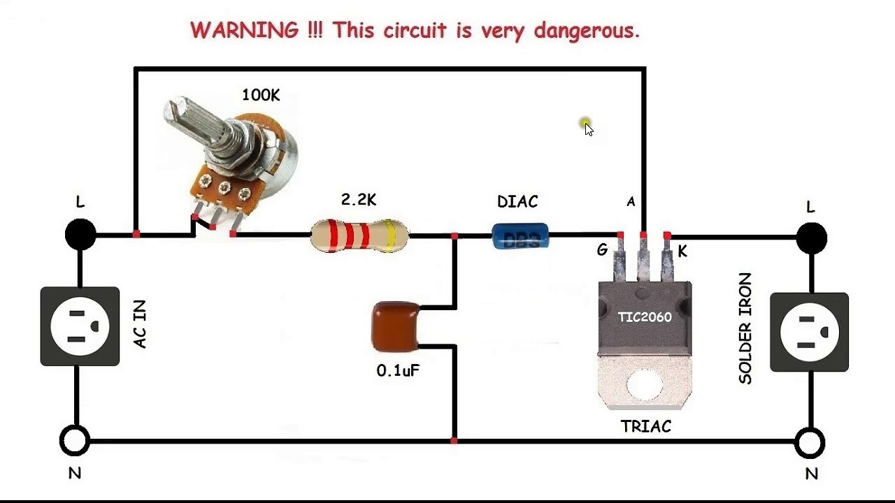
AC motor speed control circuit. how to make single phase motor speed

2 Wire Control Circuit Diagram. Motor Control Basics. Controlling three

50A DC Motor Controller Schematic.png

A Picture Showing the Constructed DC Motor Control Circuit. | Download

bldc circuit diagram - Wiring Diagram and Schematics

Building a PWM circuit to control a 90v DC motor at 20amps. Will this